Noise Measurements
Applications:
- Real-time fluctuations characterization
- Low-frequency noise spectroscopy
Options:
- Distinguishing up to four GR components
- Error ≤ 10%
- Accurate recording of noise components amplitudes
Specifications:
- Frequency range 1 Hz ÷ 100 kHz
- Preamplifier intrinsic noise SVpreampl = 2.2 ×10⁻¹⁸ V2Hz-1
- Amplifier intrinsic noise SVampl = 2.4 ×10⁻¹⁷ V2Hz-1
Description:
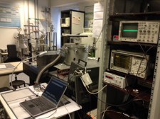
The noise measurement setup (see first figure) was improved during the PhD work of Viktor Sydoruk. This setup allows precise fitting of the noise spectra by set of the existing noise components. Additionally, it allows to distinguish up to four (five under a special conditions) generation-recombination components and to obtain their parameters with an error, which is not exceeding 10%. The fitting procedure of the spectra by set of the uncorrelated components allows precise determination of the components parameters.
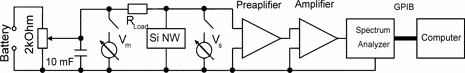
Schematically, the measurement setup is shown in the second figure. 2. A lead-acid battery is used to apply voltage to the sample. Value of the voltage can be controlled using a variable resistor of 1 kΩ. Such a supply system allows us to reduce noise pickup during the measurements. A capacitance of 9400 μF which is in parallel to the variable resistor, decreases the value of resistor to <16.7 Ω at 1 Hz. This in turn reduces the thermal noise. The sample is connected to the power supply source in series with the load resistance, RLoad. The load resistance is selected using the high-precision, low inductance resistance box decade, fabricated by IET Labs Inc. The resistance can be changed in the range from 1 Ω to 1 MΩ.
Such a circuit allows to control the bias voltage from zero to ~6.3 V voltage using liquid-acid accumulators in order to specify the measurement regimes. Short circuit and open circuit regimes can be used by changing the load resistance from 0 to ultra-high one, respectively. Because of the total capacitance (~350 pF) of the cables connected to the sample, at large values of RLoad, the measured spectra can have a roll-off in the high-frequency range. For example, at RLoad=5 kΩ the cut-off frequency is fcut-off ≈ 91 kHz , which has to be taken into account.
The multimeters allow to measure voltages VS and VM on the sample and on the working circuit, respectively. The DC current can be calculated as IS = (VM - VS)/RLoad. Applying DC voltage to the sample is necessary for specifying the working point of the device for measurements of fluctuations as shot, GR, RTS and flicker noise components in the noise spectra. The multimeters are connected to the measurement setup before and after noise measurements. This allows to measure the voltage applied to the sample, current in the circuit and to check the stability of the system: parameters of the system have to be the same before and after the noise spectra measurements. During the noise measurements the multimeters are disconnected to avoid the influence of their intrinsic noise on the whole spectra.
The noise signal is amplified by a homemade preamplifier (see second figure) with gain ≈ 173 and a commercial amplifier ITHACO 1201 with a variable gain (from 1 to 105 ). The preamplifier was designed on the basis of 2-stage amplifier biased with a low noise power source. The first amplification stage is very important in a noise measurement setup. Its intrinsic noise has to be as low as possible. The homemade amplifier has intrinsic thermal noise SVpreampl = 2.2 ×10⁻¹⁸ V2Hz-1 and the factory amplifier has the value of SVampl = 2.4 ×10⁻¹⁷ V2Hz-1 at 10 kHz. The amplified signal is measured using a dynamic signal analyzer HP35670A, which transforms the time fluctuations into the noise spectrum (in the frequency domain) by the Fourier Transform. Then the data are transferred through a GPIB interface to the computer for further analysis.
Contact:
Prof. Dr. Svetlana Vitusevich
Tel.: +49-2461-61-2345
e-mail: s.vitusevich@fz-juelich.de