IAGOS-SimLab
Simulation of IAGOS flight conditions in the laboratory
Global aerosol observation is targeted by the European research infrastructure IAGOS (In-service Aircraft for a Global Observing System) (Petzold et al., 2015), which aims to cover all essential climate variables of the atmosphere, including aerosol particles (Bojinski et al., 2014) by regular and global-scale measurements conducted on board of a fleet of passenger aircraft equipped with automated scientific instrumentation. One of the options for testing and calibrating these so-called packages, specifically the Air Quality Package P2e, is the IAGOS-SimLab.
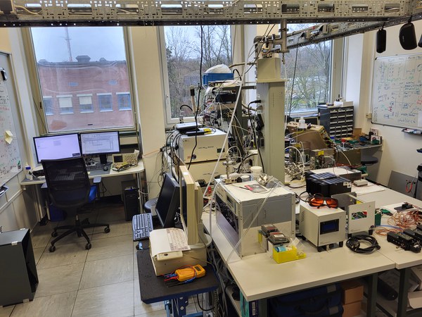
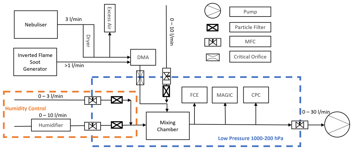
A photo of the laboratory set-up is shown in Fig. 1, Fig. 2 shows the flow schematic of the experimental set-up. We use a nebuliser to atomise the particle-retaining solution, for example an ammonium sulfate (AS) solution, to provide a steady and constant particle production in size distribution and number concentration (constant output atomiser; Model 3076, TSI Inc., Shoreview, MN, USA) (Liu and Pui, 1975; TSI Inc. Model 3076, manual). After the aerosol flow passes through a diffusion dryer tube, the relative humidity reaches levels below 5 %. The sample flow follows a charging process by passing through a radioactive Am-241 source and the classification in a monodisperse aerosol takes place by a Vienna-type differential mobility analyser (DMA; Model M-DMA 55-U, Grimm Aerosol Technik GmbH & Co. KG, Ainring, Germany).
The aerosol enters the low-pressure zone by passing through a critical orifice. The aerosol is diluted in the mixing chamber with aerosol-filtered air. The pressure is controlled by a LabVIEW programme through multiple mass flow controllers with a PID (proportional integral derivative) controller approach. At 200 hPa, the measured standard deviation was less than 0.1 hPa with an integration time of 100 s. Furthermore, the relative humidity is actively controlled by adding a stable humidified air flow into the system through the mixing chamber, which is limited to approximately 30 % relative humidity. Temperature, inline pressure, and relative humidity are measured in the mixing chamber. Water vapour can be added to test particle activation growth effects for different relative humidity levels. The volume of the mixing chamber is 500 mL with a flow rate of 10 L min−1. This leads to a flushing time of roughly 3 s and an e-folding time of 1.8 s for 63 %.
After passing through the mixing chamber, the aerosol flow is guided to the measuring instruments using individual isokinetic, iso-axial samplers located in the centre of the sample line. The diffusion losses are similar for all instruments. The flexible conductive sampling tubing length from the line to the instruments is set to 25 cm for instruments sampling at a flow of 0.6 L min−1 and adjusted proportionally to instruments with a different sampling flow. A Sky-CPC 5.411 (Grimm) is used as a well-characterised butanol condensation particle counter (Bundke et al., 2015). An aerosol electrometer is used as a traceable reference instrument for particle counting measurements (FCE; Model 5.705, Grimm). An instrument of special interest is the newly developed Moderated Aerosol Growth with Internal Water Cycling CPC (MAGIC 210-LP; Aerosol Dynamics Inc, Berkeley CA, USA). For fresh flame soot measurements, the nebuliser and the dehydration tube can be replaced by a miniature inverted flame soot generator (Argonaut Scientific Corp., Edmonton, AB, Canada). Prior studies provide greater detail (Bundke et al., 2015; Bischof, 2022).
The DMA is operated stepwise for 30 s for each voltage level corresponding to different particle sizes starting at an upper limit of 140 nm and going down to 2.5 nm. This size limit is set by the fact that we use the 8.8 cm tube and a 6 L min−1 sheath flow for a high accuracy and low-mobility size half-width. To avoid transition effects and to achieve a uniform aerosol inside all measuring instruments, the first 15 s for each particle size setting of the DMA are excluded from the dataset. Earlier experiments have shown that this time is sufficient to flush the system.
The inverted flame soot generator is operated with an oxidation-air-to-propane ratio of 7.5 L min−1 air to 0.0625 L min−1 propane. This flow setting ensures stable low organic carbon soot production (Bischof et al., 2020; Kazemimanesh et al., 2019).
Further information can be found in the publications listed below.
More on the topic
Related publications
Contact

Dr. Ulrich Bundke
Senior Scientist Head of group "Global Monitoring"
- Institute of Energy and Climate Research (IEK)
- Troposphere (IEK-8)
Room 3049b

Patrick Weber
PhD student
- Institute of Energy and Climate Research (IEK)
- Troposphere (IEK-8)
Room 3046